

![]() 1. SELECTION TOOL
1. SELECTION TOOL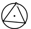
Use this tool to select an object. Drag the selected figure to move it. When you move an entire figure, and a point is drawn a figure of for a point in circumference like a right figure, you can move it over the figure. Double-click on a figure to change its properties. Unless continuous drawing mode is enabled, this tool is chosen automatically after each drawing operation.
2. DISPLAY MODE SWITCHING TOOLS
This tool changes the display mode of the selected figure. The display modes available are visible, invisible, locked, and deleted.
![]() Hide a figure: Change the display mode of the figure to invisible. Clicking on a figure hides it by changing its display mode to invisible. To make it visible again, change its mode in the list of figures.
Hide a figure: Change the display mode of the figure to invisible. Clicking on a figure hides it by changing its display mode to invisible. To make it visible again, change its mode in the list of figures.
![]() Lock a figure: Locked figures cannot be moved by dragging. After selecting this tool, click on a figure to lock it. To re-enable movement by dragging, select the figure from the list of figures.
Lock a figure: Locked figures cannot be moved by dragging. After selecting this tool, click on a figure to lock it. To re-enable movement by dragging, select the figure from the list of figures.
![]() Delete a figure: After selecting this tool, click on a figure to delete it. Note that deleting a figure also deletes all dependent figures as well. (E.g. deleting a vertex of a triangle deletes the triangle as well, but the other vertices remain.)
Delete a figure: After selecting this tool, click on a figure to delete it. Note that deleting a figure also deletes all dependent figures as well. (E.g. deleting a vertex of a triangle deletes the triangle as well, but the other vertices remain.)
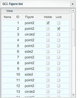
Display the list of figures
Editing is not possible while the list is being displayed. The display state of each figure is shown. Clicking on the checkboxes for a figure changes its display mode. Use these checkboxes to undo the hiding or locking of a figure.
![]() 3. CONTINUOUS DRAWING MODE SWITCHING TOOL
3. CONTINUOUS DRAWING MODE SWITCHING TOOL
This tool enables or disables continuous drawing mode. When disabled, the selection tool is used after performing a drawing operation. When enabled, the same drawing tool is used repeatedly after a drawing operation. Click on the left side checkbox to toggle it. Continuous drawing mode is particularly useful when repeating the same drawing operation.
4. POINT TOOLS
Add a point. Whether the point is named or unnamed can be changed afterwards. Midpoints, intersection points, points of linear and point symmetry, and rotated points depend on other figures. Therefore these types of points may change (be moved or deleted) when the dependent figure is changed (e.g. moved, deleted).
![]() Point (without label)
Point (without label)
![]()
Add a point. To add a point to a figure, move the mouse cursor over the figure first. The figure flashes. Click on the flashing figure to add a point to it.
![]() Point (with label)
Point (with label)
Add a point with a label such as A, B, etc. New points are given the labels of A, B, etc. in the order they were added. Other than having a label, there is no difference between a point with and without a label.
The name is placed to the left side of the point. To move the name, drag it while holding down the CTRL key.
![]() Midpoint
Midpoint
Add a midpoint for two points or for a segment. To add the midpoint, click on the two points of the segment. Make sure that the correct figures are selected when adding the midpoint. Midpoints are added to each side for figures with multiple sides.
![]() Intersection
Intersection
Click on two figures to add the point(s) of intersection of those figures. Make sure to select the correct figures when adding point(s) of intersection. Points of intersection with polygons such as triangles are not supported. To add points of intersections with such figures, add a segment for each side and use that segment for adding the point of intersection.
![]() Point of line symmetry
Point of line symmetry
Add a point by taking the reflection of an existing point in a line (ray). Click on the line (ray) to be used as the axis first. After that, select the point to transform. It is not possible to use a segment or a side of a figure as the axis. In such cases, add a line first and use reflection in that line to add the symmetry point. After that, hide the line
![]() Point of point symmetry
Point of point symmetry
Add a symmetric point for a point. Select the point to use as the center of symmetry first. After that, select the point to transform.
![]() Rotation of a point
Rotation of a point
 Add a point by rotating a point around another point. Enter the angle of rotation first. After that, click on the center of rotation, and finally select the point to transform.
The values for x and y express the coordinates of the point. In general, modifying the numerical values for the coordinates moves the point. However, when the point is part of a figure, it is not always possible to move it by specifying new coordinates.
Properties for points
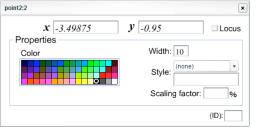
The values for x and y express the coordinates of the point. In general, modifying the numerical values for the coordinates moves the point. However, when the point is part of a figure, it is not always possible to move it by specifying new coordinates.

To resize an individual point, change the "width" in this dialog. Use “style” to add, remove, or change the name of a point. The name consists of a single Latin letter or a single-digit number. Besides printed letters, a cursive l () is also available as a special character. When adding a name to a previously unlabeled point, the scaling factor is set to 50%.
Graphics can be embedded as labels as well. Flash data (SWF files) and JPEG images are supported. However, changing the size of graphics is not supported. Besides for illustrations and photos, movie clips can also be used for vertex names. Use JPEG images to display characters that are not available in the Latin alphabet.
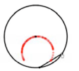 Click on the check box for "Locus" to draw the locus of a point. The locus is drawn in a semitransparent manner using the color of the point.
The figure to the right shows a circle and a chord which has a red middle point. When one end of the chord is fixed and the other end is moved on the circle, the red point draws the trace shown in the figure.
![]() 5. PASTE TOOLS
5. PASTE TOOLS
Graphics can be attached to points or to the background. Flash data (SWF files), as well as JPEG images, can be used. Note that changing the sizes of graphics is not supported.
Paste a file in a point
Attach a graphic file to a point. Clicking on a point opens a dialog box. Choose the graphic file to attach to the point.
Paste a file in background
Load a graphic file as the background. Choose the graphic file in the dialog box. The current version of GCL editor does not support the replacement of background graphics. Choosing another file adds the new file. Edit the GCL file directly by a text editor to remove the background.
6. LINE TOOLS
Add a new line. Clicking at a place without points or characters automatically adds a new unnamed point there. As lines depend on points, other lines or circles; lines may change (be moved or deleted) when the dependent figure is changed (e.g. moved, deleted).
![]() Line
Line
Add a line. First, click on a place (a point or a background). A line will appear. After that, click again at another place to create the line. Drag the line using the selection tool to rotate it around one of its points.
When you drag the first point and move, you can move the whole straight line. If you click on a point in the second click, you make a line which is on the two points. Then, you can move the line by dragging and moving the two points.
![]() Ray
Ray
Add a ray. Adding and moving rays is done in the same manner as with lines.
![]() Segment
Segment
Add a segment. Click on the two ends of the segment to add it. Moving the segment is done in the same way as with lines on two points.
![]() Parallel line
Parallel line
Add a line parallel to an existing line. First select the existing line or segment. The selected line starts flashing. After that, click on the point through which the parallel line should pass. It is also possible to select the line and the point in reverse order. Note that adding lines parallel to rays or sides of triangles is not supported.
![]() Perpendicular line
Perpendicular line
Add a line that is perpendicular to an existing line. First, click on the existing line. The selected line starts flashing. After that, click on the point through which the perpendicular line should pass through. It is also possible to select the line and the point in reverse order. Note that adding lines parallel to rays or sides of triangles is not supported.
![]() Perpendicular bisector
Perpendicular bisector
Add a perpendicular bisector for two points of a segment. To add, select the two points or the segment. Adding a perpendicular bisector to a side of a figure is not supported.
![]() Bisector of an angle
Bisector of an angle
Add a bisector to an angle. To add a bisector to angle ∠ AOB, click on the points A, O, B in that order.
![]() Tangent line to a circle
Tangent line to a circle
Add tangent lines to a circle from a point. Click on the circle first. The circle starts flashing. After that, click on a point. Two tangent lines to the circle are added that pass through the point. Selecting the circle and the point in the reverse order is also supported. When selecting the circle first, the flashing circle may occasionally become invisible due to an issue with the flash timing.
![]() External common tangent to two circles
External common tangent to two circles
Add the external common tangent lines for two circles. Select two circles to add the two external common tangent lines for them. Tangents are added even in the case when the locations of the circles do not allow them to be drawn. In such case, tangents are invisible until circles are moved to locations where common tangents can be drawn. When selecting the circles, the first circle may occasionally become invisible due to an issue with the flash timing.
![]() Internal common tangent to two circles
Internal common tangent to two circles
Add construct the internal common tangent lines of two circles. Select two circles to add the two internal common tangent lines for them. Tangents are added even in the case when the locations of the circles do not allow them to be drawn. In such case, tangents are invisible until circles are moved to locations where common tangents can be drawn. When selecting the circles, the first circle may occasionally become invisible due to an issue with the flash timing.
Properties for lines
Dialog box for property setting of the line is opened when you double-click on the line.
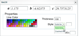 a, b, and c are values for the line’s equation ax + by + c = 0. Modifying these values generally moves the line. However, lines that depend on other figures cannot be moved this way.
The thickness of the line is shown as percentage of the default width. Select from solid or dashed line in “style.” For dashed lines, an additional parameter sets the length of the gaps between dashes (percentage).
![]()
Thickness 5 ----- Thickness 5 ----- Thickness 5------- Thickness 5
Solid ------------- Dashed, 50% ---- Dashed, 90% ---- Dashed, 50%
7. CIRCLE, ARC AND SECTOR TOOLS
Add circles, arcs, and sectors. Clicking on a place on the pane without figures or labels adds a point without
a label there.
When a circle (arc, sector) has points that depend on other figures, and the dependent figure is changed (moved or deleted), the circle also changes (is moved or deleted).
![]() Circle (Center)
Circle (Center)
Add a circle by selecting the center and a point on the circle. Select the center first. After that, move the mouse to change the radius, and click to add the circle. After adding the circle, moving the center using the selection tool moves the circle. Using the selection tool on the circle changes the radius of the circle. Clicking on an existing point after selecting the center adds a circle that passes through that point. If that point is moved afterwards, the radius of the circle is adjusted automatically.
![]() Circle (Three points)
Circle (Three points)
Add a circle by specifying three points to pass through. Click on three places to add the circle. Moving any of the points changes the position and the radius of the circle.
![]() Circle (Diameter)
Circle (Diameter)
Add a circle by specifying its diameter. Select two points to add the circle that has those two points as its diameter. Adding the circle by selecting a segment is not supported. After the circle has been added, moving the ends of the diameter changes both the position and the radius of the circle.
![]() Circumscribed Circle
Circumscribed Circle
Add the circumscribed circle to a triangle. Select a triangle to add the circumscribed cirle to it. Note that adding a circumscribed circle to three points connected by segments is not supported.
![]() Inscribed Circle
Inscribed Circle
Add the inscribed circle to a triangle. Adding is done the same way as with circumscribed circles.
![]() Arc (Center and two points)
Arc (Center and two points)
Add an arc by specifying the center and the two ends. To add an arc AB that has point O as the center, click on the points O, A, B in that order. The arc is drawn anticlockwise from A to B. After the arc has been added, A and B can be moved on the circle to change the length of the arc. The radius of the arc can be changed in the properties dialog box.
![]() Arc (Two points on circumference)
Arc (Two points on circumference)
Add an arc by specifying two points on an existing circle. Select two points on the circle to add the arc. To draw an arc connecting two figures, add a circle first. After that, add intersection points of the circle with the figures. Finally, add the arc using the circle and the points.
![]() Sector (Center and two points)
Sector (Center and two points)
Add a sector. The usage of this tool is identical to that of Arc (Center and two points).
![]() Sector (Two points on circumference)
Sector (Two points on circumference)
Add a sector. The usage of this tool is identical to that of Arc (Two points on circumference).
Properties for circles, arcs and sectors
Double-click on a circle, arc or sector to open the properties dialog box.
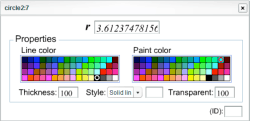
Changing the value for “r” changes the radius of the figure.
Note that the radius cannot be changed when it is bounded by two points. Changing of the line style is done in the same manner as with straight lines. In addition, the paint color and transparency can be selected for circles and sectors. Transparency can be specified as a percentage value.
A value of 100 means transparent and 0 means opaque.
The color of a partially transparent figure is mixed with the colors of overlapping figures.
Newer figures are created on top of existing figures of the same type. The overall priority is as follows (top to bottom): points, lines, circles, polygons. (This is the same as the order of drawing tools.)
8. POLYGON TOOLS
Add a polygon such as a triangle or a quadrangle. When the polygon depends on existing points, changing (moving or deleting) the dependent points causes the polygon to be changed (moved or deleted).
![]() Polygon tools
Polygon tools
Add a polygon such as a triangle or a quadrangle. When the polygon depends on existing points, changing (moving or deleting) the dependent points causes the polygon to be changed (moved or deleted).
The line style and the paint color can be changed in the properties.
![]() Quadrangle
Quadrangle
Add a quadrangle. Other than the number of vertices, it is done the same way as with triangles.
![]() Polygon
Polygon

Add a polygon. Enter the number of vertices first. After that, add the polygon similarly to the case for triangles. The maximum number of vertices is 20.
![]() Regular Polygon
Regular Polygon
 Add a regular polygon. First, similarly as with polygons, enter the number of vertices. Regular polygons are created by specifying a side of it (two vertices). The polygon is displayed after selecting the first vertex. Click on another point to select the other end of the side. Two regular polygons share the same side. Choose from the two polygons to finish adding the polygon. The maximum number of sides is 12 (regular dodecagon).
Properties for polygons
Double-click on a polygon to open the properties window.
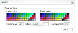
Changing properties is done in the same way as with circles,
arcs and sectors.
9. MEASUREMENT AND SYMBOL TOOLS
These tools allow you to add measurements of distances, angles, and areas, and to add symbols of equal length, parallelism, or equal angle
![]() Measurement (Length)
Measurement (Length)
 Show the distance between two points. Select two points and their distance is shown. The distance is initially shown at the center between the two points. Drag the distance display to move it to a different location.
Properties for lengths
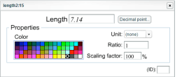
Double-click on the distance display
to open the properties window.

The length (distance) cannot be changed from the dialog box. Click on “Decimal point…” to change the number of floating-point digits to display.
Click on the down arrow beside “Unit” to choose a unit for the displayed value.
Changing the ratio adjusts the displayed length by the same rate. Adjust scaling factor to change
the size of letters.
Changing the color changes both the color of the displayed value and the lines that point to the measurement range.
![]() Measurement (Angle)
Measurement (Angle)

Show the measurement of an angle. For an angle ∠ AOB, click on the points A, O, B in that order. The second point becomes the vertex. The measured value is displayed on the bisector of the angle.
![]() Measurement (Area)
Measurement (Area)
Show the area of the polygon. Click on the polygon to add the area display. Note that areas displayed for twisted polygons may be incorrect.
Convex polygon -- Concave polygon --Twisted polygon
Properties for areas
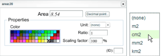
Double-click on the area display to open the properties window. Other than the difference in the units, it is identical to the properties for lenghts.
Symbol (Length)
![]()
Add a length symbol. These symbols are used to indicate segments with identical lengths. Select two points or a segment to add a symbol. Initially symbols are added to the center. After adding, the symbol can be moved by dragging. Automatic adding of symbols for segments of the same length is not supported.
Symbol (Parallelism)
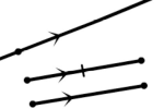
Add a parallelism symbol. Select a line or a segment to add a symbol to. After adding, the symbol can be moved by dragging. Automatic adding of symbols for parallel lines is not supported.
Properties for line symbols
Double-click on a symbol to open the properties window.

Five kinds of symbols are available for segment length, and three kinds of symbols are available for parallelism. The scaling factor adjusts the size of the symbol. For the symbols for parallelism, the direction can also be changed.
Symbol (Angle)

Add an angle symbol. For an angle ![]() AOB, select the points A, O, B in that order. The second point becomes the vertex of the angle.
AOB, select the points A, O, B in that order. The second point becomes the vertex of the angle.
Properties for angle symbols
Double-click on the symbol to open the properties window. The value of the angle cannot be changed. The number of floating-point digits can be adjusted in the same way as for distance measurement.
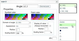
Three ranges of angles (“Domain of angle”) can be used for displaying angles. In addition, six types of symbols are available for the angle. The default symbol is the single arc. The paint color is adjustable as well.
![]() 10. SPECIAL POINT TOOLS
10. SPECIAL POINT TOOLS
Add the center of one of six special circles to a triangle. (Three centers in the case of excenters.) Note that these tools share the same icon. Please make sure that the right tool is selected.
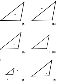
(a)
Center of gravity
(b)
Circumcenter
(c)
Incenter
(d) Orthocenter
(e)
Excenters
(f)
Center of Nine Point Circle
